|
Development of the
Sandflea and Redbud Garden Railway
Trestles,
Bridges, and Tunnel Portals
I had about 20 feet of trestle in three locations and three bridges to construct and put in place.
I started first with the lowest trestle, elevated about 5-7 inches high.
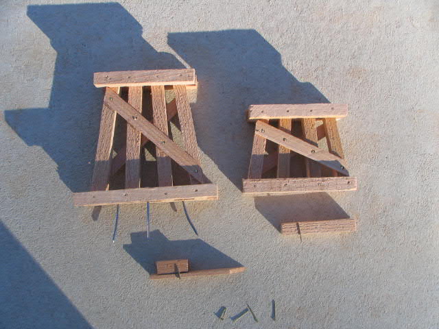 To make each trestle bent, I drew a template on a board to maintain uniformity in angles and certain
widths. All bents were made of strips cut from cedar fencing. The legs were square and the cross-ties
were 0.2 inches thick. The wood was glued together and secured with brass nails. A base of cross pieces was
placed at the bottom of each bent to rest it on a concrete base. Nails through the base secured it to
the concrete base.
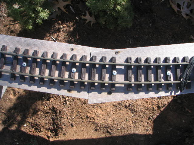
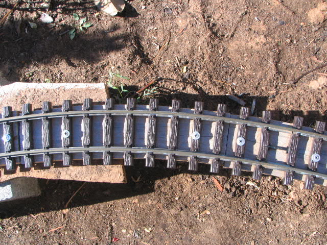 The stretches of track to be on trestle
have been resting on concrete blocks and cedar fencing for more than a year (left). I began by removing each
fenceboard and cutting it about 0.5 inch inside the "weathering marks" left by the track on the board.
This left a substrip about 2.5 inches wide under the track. The track was rescrewed onto the strip
under the track.
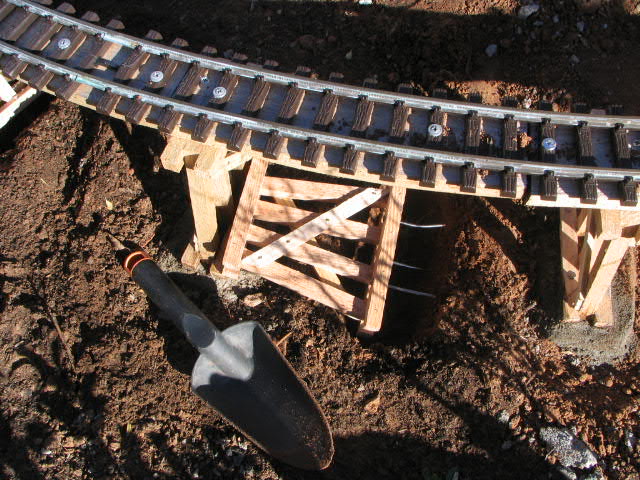
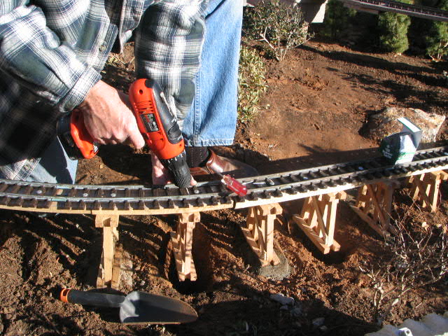
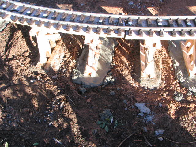
The bents were spaced at 6.5 inches apart. I began by digging a
shallow hole under the location of each bent (far left).
The bent was then screwed onto the track substrip, leaving the bent hanging from the track.
I then poured concrete into the hole up to the level of the base of the bent. After a few hours, I trimmed the cement
back to a rectangular form.
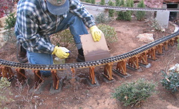
Below is a photo of me applying Thomson's WaterSeal Waterproofer Plus Clear Wood Protector.
This sealer is supposed to retain the natural wood brightness and prevent browning of the wood with age.
I applied it with a squirt bottle to cover each bent thoroughly.
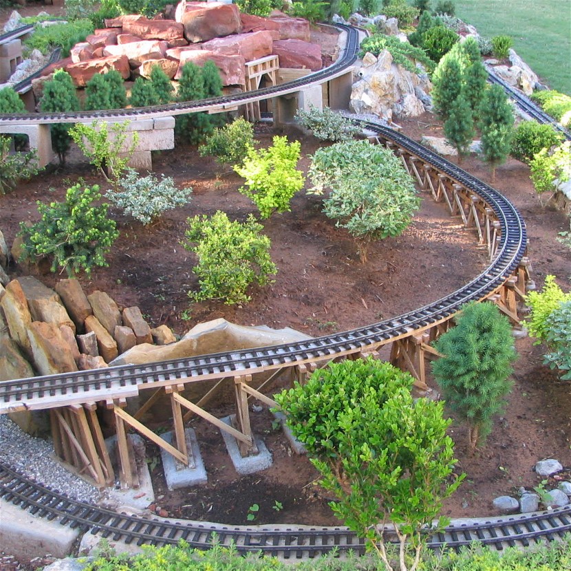
I next added supports tying the bents together. This completes the trestle (see photo below).
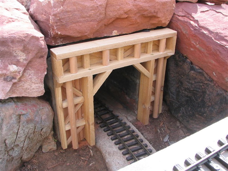
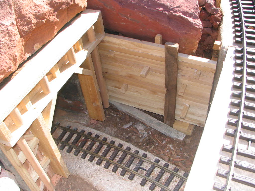
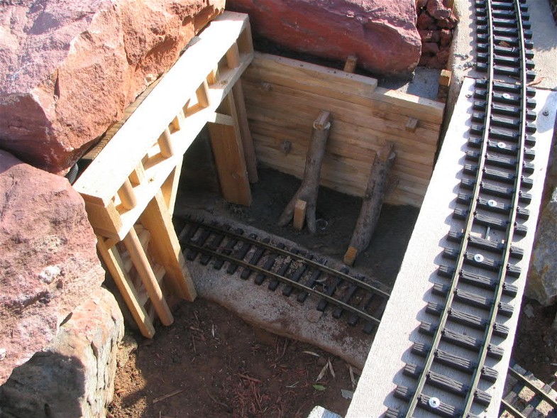
In June of 2006, immediately after completing the first trestle, I built a portal
for the west end of the tunnel. Figure 1 above on the left shows the portal in place and the adjacent
unsupported wall beside the portal. The portal was fastened to the brick with concrete anchors and screws.
Figure 2 above shows a retaining wall in place; concrete was
poured behind the retaining wall for strength. Figure 3 above shows the
log supports placed to appear to hold up the retaining wall.
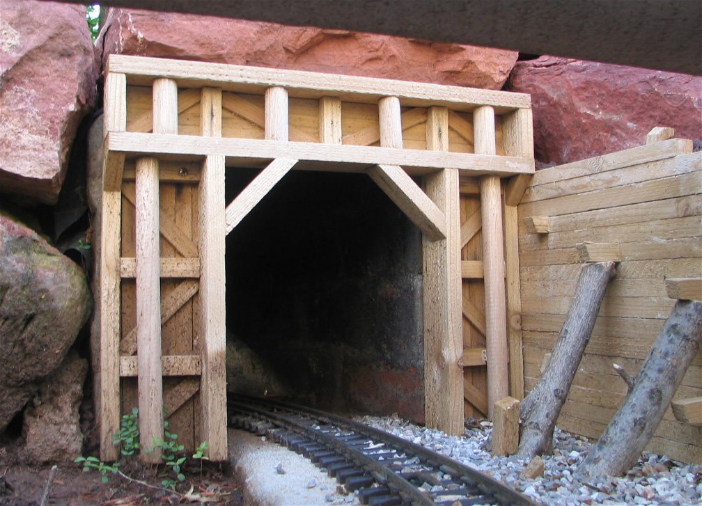
The photo below shows the finished portal with ballast added on the right side (concrete underneath).
The left side must wait for completion of the trestle passing over the front of the
tunnel portal. Some trim around the top and left side of the portal will be added later.
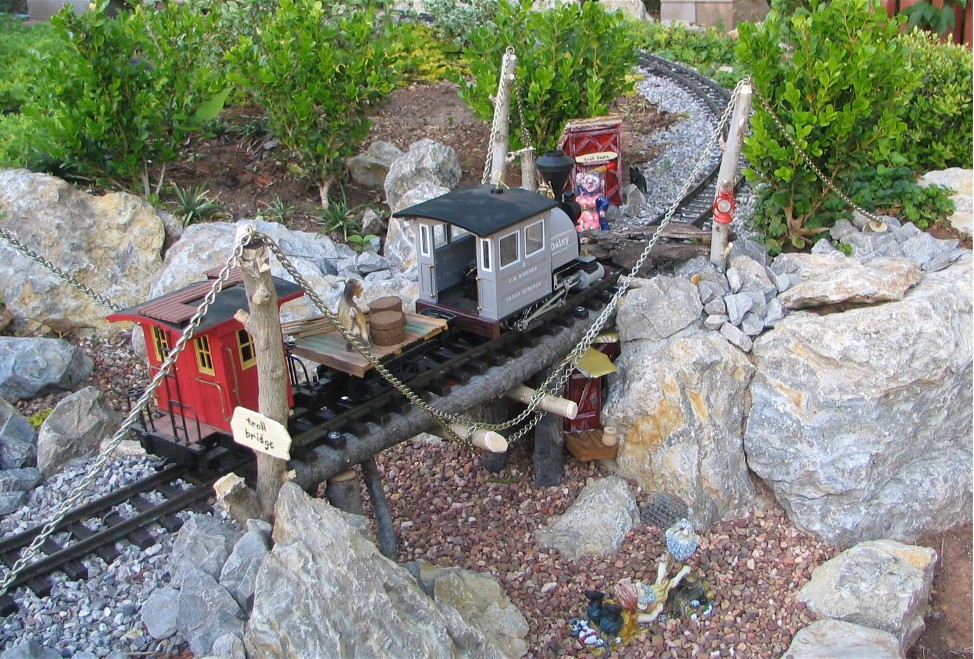
I next added a bridge over one of my dry gullies. The bridge is unique in construction and in real life
would be of questionable practicality. It is essentially a suspension bridge, with two log girders
held up by four chains held above by vertical log posts and anchored into the ground on the ends.
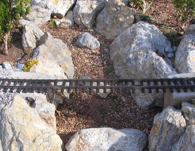
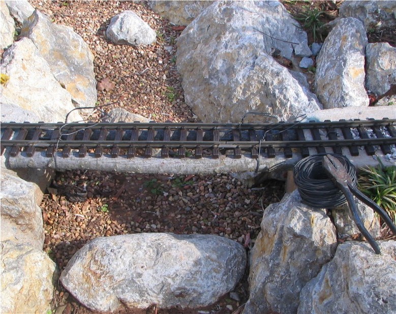
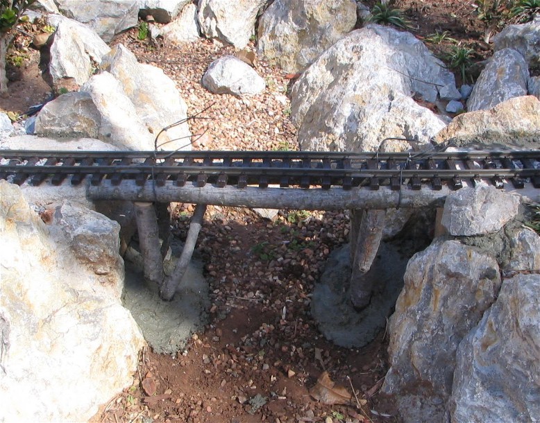
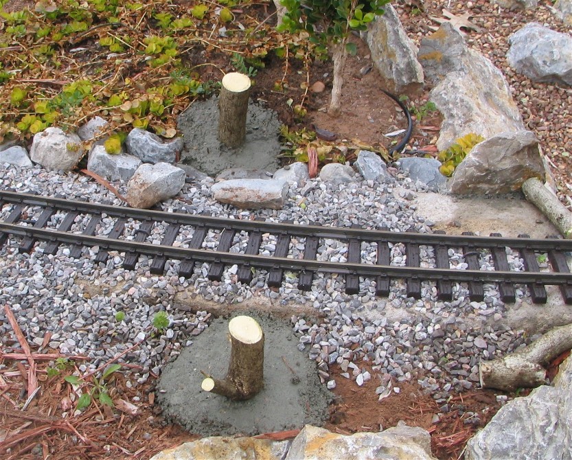
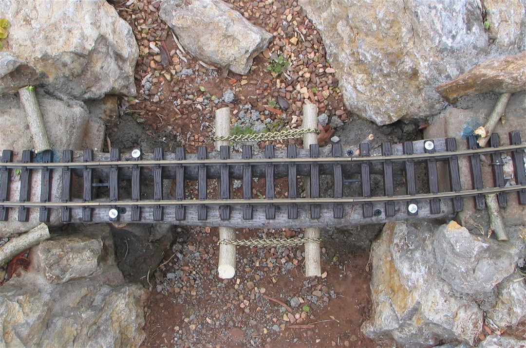
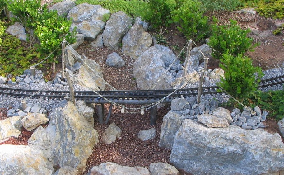
Below are a series of photos showing the construction at various stages: the
beginning span (Fig. 1), the supporting log beams wired on temporarily (Fig.
2), the supporting vertical logs cemented into place (Fig. 3), the anchoring
logs cemented into the upland area (Fig. 4), the cross-tie logs for
anchoring chains to the bridge (Fig. 5), and the anchoring chains in place
(Fig. 6). The final large photo shows the completed bridge - the Troll Woman has placed logs across the
track to stop the train and demand the toll.
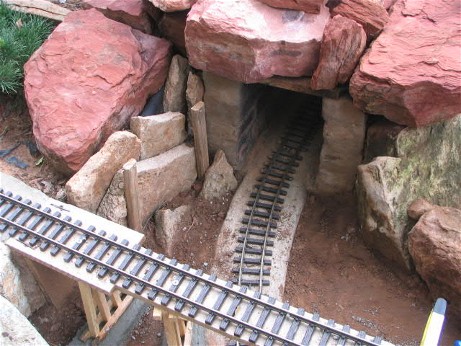
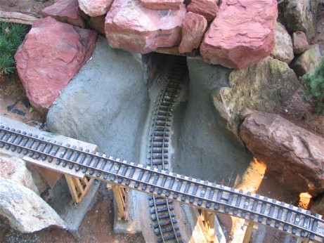
Below are three photos showing construction of the entrance to the east portal of the tunnel in September 2006.
The left photo shows the portal prior to new work. Concrete pieces and two stakes are shown
supporting the dirt embankmnent on one side. The concrete pieces were left in place; the stakes
were removed. A fairly dry concrete mixture was stacked on both sides to create simulated rock
walls. Wadded tinfoil was pressed onto the surface to rough it slightly. The middle photo
shows the fresh concrete. I then spray-painted the cement with various colors to simulate red sandstone.
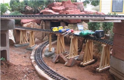 The photo at the left shows the second trestle under construction in September 2006. Two more bents
(not shown) will be added to the left of those shown. No cross pieces will be added to this short
trestle. The bents are spaced 8 inches apart.
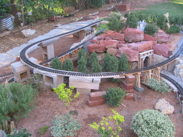
In September 2006 I began work on the third and final trestle. It is about 20 feet in length. The photo
below shows three bents in place. Note that most of the trestle is temporarily supported by stacks of
bricks and concrete blocks. Bents are erected on each side of a temporary support column
before the column is removed.
Back to the top of the page
Return to Garden Railway index page
|

